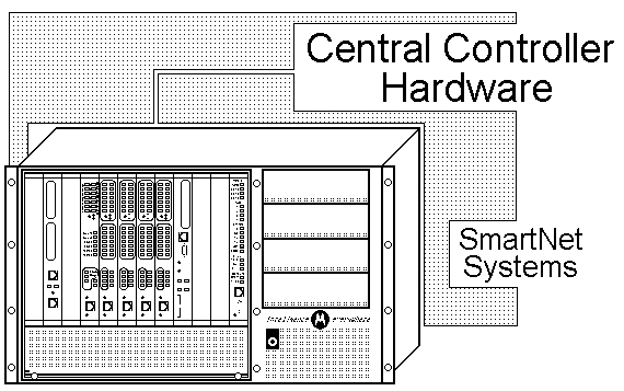
MTC-3600™ Controllers are the site call processing units required for operation in an analog SmartNet Trunking radio system. MTC-3600 is the evolution of the MC-6809-based SmartNet Central Controller.
|
 |
|
|
|
|
|
|
|
MTC-3600™ Controller is the central call processing equipment that uses advanced PowerPC processing with CompactPCI technology. It provides trunked operation in Single Site Trunked Radio Systems or Motorola Simulcast Trunked Systems. When combined with other equipment, the MTC-3600 Controllers yield leading edge trunked radio operation, system management and control. In addition to supporting features like Selective Calls, Group Calls and Push to Talk ID Display, key features and benefits yielded by the controller are listed below.
The MTC-3600™ combined with ASTRO™ equipment yields leading edge trunked radio operation, system management, and control. With SmartNet ASTRO Secure, transmissions can be protected from unauthorized monitoring with digital encryption methods.
MTC-3600™ has been developed to support the continuing life of 3600-baud control channel systems. The MTC-3600 is a functional replacement of the MC-6809-based SmartNet Central Controller.
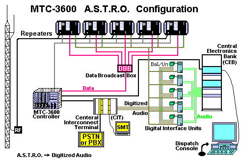
The MTC-3600 supports all three modes of operation (that is, analog, ASTRO and mixed mode). SmartNetII++ uses Motorola's proprietary ASTRO technology for digital operation. For digital communications, the MTC-3600 interfaces with a Data Broadcast Box (DBB), which forwards control information between the MTC-3600 and the ASTRO-capable base stations. The base stations extract and embed control information in the digitized audio signal.
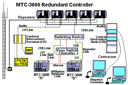
For dispatch calls, the Central Electronics Bank (CEB) sends console audio to the Digital Interface Unit (DIU). The DIU digitizes the voice signal and sends the signal to the base station for transmission. The DIU also converts inbound digital audio to analog. SmartNetII trunked radio systems can operate in analog, ASTRO or mixed modes. The DIU also interfaces three-wire audio to Balanced/Unbalanced Converter, converting to four-wire audio that in turn interfaces to the Central Interconnect Terminal (CIT).
The MTC-3600 trunking controller provides site control for standalone SmartNetII++ systems and replaces Motorola's MC-6809 processor-based site controller. The MTC-3600 has been designed to extend the reliable MC-6809 controller functionality into the future and to be a drop-in replacement for legacy MC-6809 systems.
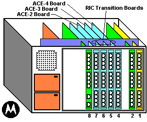
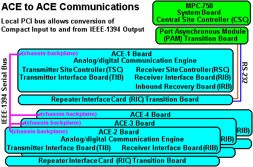
Primary site control operations occur on the MTC-3600 system board (MCP-75O). Many supporting operations that were performed by peripheral MC-6809 controller cards (e.g., Receiver Site Controller, Transmitter Site Controller, etc.) have been consolidated into the MTC-3600's ACE-1 (Analog/digital Communications Engine) board.
Since the MTC-3600 was designed as an emulator of the MC-6809, system and diagnostic messages still refer to the appropriate peripheral MC-6809 components, which are now functions rather than actual MC-6809 components.
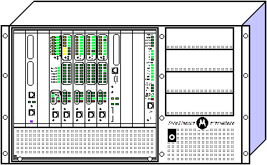
The MTC-3600 in a stand-alone SmartNetII++ system contains the components shown in the overhead. These components are housed in a Motorola CPX-2408 CompactPCI chassis that includes a 400-watt power supply. (Dual 400-watt power supplies are an option.) The MTC-3600 has eight card slots, one system slot and seven peripheral slots. Processing boards are located in the front bay, attached to the backplane. Each processing board has a corresponding transition card installed on the other side of the backplane, which provides I/O ports. Refer to the table on the following page for a brief description of these component boards.
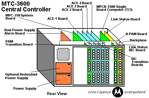
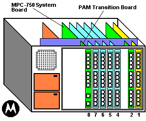
In the MTC-3600, the processing boards (the system board and the ACE boards) are located in the front of the chassis and plug into the mid-plane. The transition cards (PAM and RIC cards) are located at the back of the chassis and plug into the other side of the back plane. The PAM (Port Asynchronous Module) board is a transition board for the MCP-75O system board and the system components controlled by the MTC-3600 central site controller.
The PAM (Port Asynchronous Module) board provides physical ports for the SMT, Alarms, CIT, and Redundant Controller Affiliation Link.
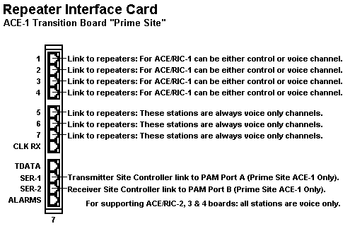
The RIC (Repeater Interface Card) card is a transition card, which provides connection ports between the MTC-3600 and base station repeaters, and serial links to the PAM board.
| Functions of the MTC-3600 System Component Boards: | |||
|---|---|---|---|
Component Name |
Transition Card |
Slot |
Description |
| MCP-75O System Board |
PAM |
8 |
MCP-750 is a PowerPC based system board. Contains a Compact Flash memory card that stores the code plug and controller software. Performs MC-6809 Central Site Controller Function. Port Asynchronous Module (PAM) transition board provides physical ports for the following:
|
 |
|||
| ACE-1 Board | RIC | 7 | Analog/digital Communications Engine ACE-1 Digital signal processor which supports up to 7 base station channels. First four channels can be control channels. All 7 channels can be voice channels.
Performs the following MC-6809 controller logical functions for the base stations connected to it:
Repeater Interface Card (RIC) transition board provides connection ports between the MTC-3600 and base station repeaters, also serial links to the Port Asynchronous Module (PAM) transition board (see above). |
 |
|||
| ACE Boards 2,3,4 | RIC | 4-6 | Up to 3 additional ACE boards, each supporting up to 7 voice-only base station channels. Performs the following MC-6809 controller logical functions for the base stations connected to it:
Repeater Interface Card (RIC) transition boards provide connection ports between the MTC-3600 and base station repeaters, also serial links to the Port Asynchronous Module (PAM) transition board (see above). |
 |
|||
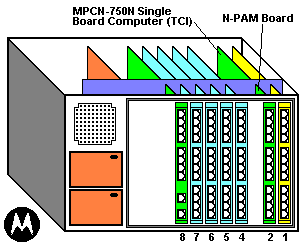
| MCPN-75O Trunked Console Interface (TCI) Board | NPAM | 2 | The MCPN-75O as a TCI Board provides the interface to dispatch consoles. It supports connections to up to two Central Electronics Banks (CEBs) that connect to the operator consoles.
(N = Non-system board) |
 |
|||
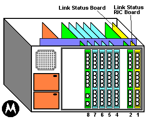
| Link Status Board (LSB) | LSB - RIC | 1 |
|
 |
|||
| Alarm Board | ALARM | 11 | Available only for systems that use the optional dual power supply configuration. Provides relay closures to alert the user if one of the power supplies falls. |
|
|||
The MTC-3600 transition cards connect to other site devices through RJ connectors at the back of the transition boards.
The MTC-3600 connects to each base station repeater with one cable from one of the first seven RIC card connector ports. Any of the first seven connector ports can connect to a voice channel repeater. To serve as a control channel, at least one base station repeater must be connected to connector ports 1-4 on the RIC card opposite the ACE-1 board (slot 7).
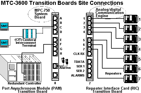
If connector ports 1-4 all have connections to base station repeaters, the MTC-3600 uses one channel as a control channel and the other three channels as voice channels. The MTC-3600 can use any of the base station repeaters connected to connector ports 1-4 as the control channel. Control and voice channels use the same cables.
These links carry voice channel control signals, control channel data and repeater control/status signals.
For systems using a separate terminal or personal computer (PC) for the System Manager's Terminal (SMT), the MTC-3600 connects to this terminal with an RS- 232 cable from connector pout C on the PAM card to a serial pout on tl4terminal or personal computer. (The PAM card is opposite the MCP-75O system board in slot 8.) If using terminal emulation software, configure the connection through a COM port on the PC at 4800-baud, no parity, 8 data bits and 1 stop bit.
Another option is Site Lens - a PC-based network management product that includes "SMT Access" a terminal emulating software designed to interface to the MTC-3600.
For systems offering the Centralized Interconnect Terminal (CIT), the MTC-3600 connects to the CIT's MCB card with an RS-232 cable from connector port C on the PAM card. (The PAM card is opposite the MCP-75O system board in slot 8) The MTC-3600 sends CIT command over this connection, along with SMT data.
The MTC-3600 connects to an Alarm Indicator device with a cable from the Alarms Active/Idle connector port on the PAM card located in slot 8. This dry contact link conveys major and minor alarms to the Alarm Indicator device.
The MTC-3600 connects to the base stations using RJ-45 connectors on the RIC card
Connections between MTC-3600 boards occur over the following paths:
A local PCI bus within the MCP-75O and MCPN-75O boards allow for conversion of CompactPCI input to IEEE-1394 output and vice versa.
Communication between the MCP-75O system board and the ACE-1 board occurs over two physical RS-232 interfaces that use 8 conductor cables and RJ-45 connectors.
One interface, cabled between the PAM card's connector port-A and the RIC-1 card's connector port SER 1, support the TSC link between the MCP-75O and the ACE-1 boards.
The second interface, cabled between the PAM card's connector port-B and the RIC-1 card's connector port SER 2, support the RSC link between the MCP-75O and the ACE-1 boards.
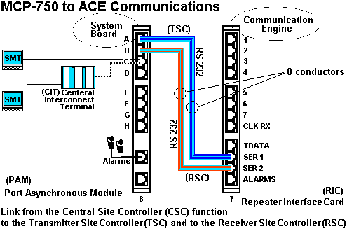
The Transmitter Site Controller (TSC) and Receiver Site Controller (RSC) are functions that run on the Primary Site Asychronous Communications Engine (ACE-1) board.
For additional detail concerning the interconnection and relationship of the MCP-75O and ACE boards, see the MTC-3600 Installation and Configuration Booklet, 68P81000Y37, latest revision.
The ACE-1 board communicates with up to three Analog/digital Communications Engine (ACE) boards over the IEEE-1394 Serial Bus. This connection supports communications between the Receiver Interface Board (RIB) and Transmitter Interface Board (TIB) functions for the channels controlled by other ACE boards and the Transmitter Site Controller (TSC), Receiver Site Controller (RSC) and Inbound Recovery Board (IRB) functions that are on the ACE-1 board. ACE-2, ACE-3, and ACE-4 boards do not communicate directly with other MTC-3600 components.
For additional detail concerning the interconnection and relationship of the ACE boards, see the MTC-3600 Installation and Configuration Booklet, 68P81000Y37, latest revision.
The MTC-3600 uses CompactPCI single-board computers for site control, digital signal processing and peripheral controller options. Transition cards provide I/O access from the rear of the chassis. This section describes the following MTC-3600 component boards:
The MCP-75O system board hosts the controller software and performs the CSC (Central Site Controller) function. The MCP-75O connects to the backplane of the MTC-3600 chassis in the system slot (8), which is also labeled CPU. The system slot is responsible for system initialization, configuration, PCI bus arbitration and system interrupt and error handling.
The system board has a bootable, IDE Compact Flash Memory card, which emulates an IDE disk drive and stores the system code plug information and controller software. This memory card can be replaced in the field, if necessary. It is shipped from the factory fully configured with system information.
Four serial ports route to backplane connectors, accessible through the Port Asynchronous Module (PAM) card. The MCP-75O system board also possesses an Ethernet controller with a lO/lOOBaseT port located on the front panel. The Ethernet port is used for loading software updates and reconfiguration information. For more information on these processes, refer to the booklet, MTC-3600 Expansion Information.
The MCP-75O system board uses a Port Asynchronous Module (PAM) transition card. For more information about this card, refer to the section, PAM Card, later in this web page.

| Front panel elements of the MCP-75O board: | ||
|---|---|---|
| Element | Color | Description |
| Ethernet Port | - | Provides a RJ-45 connector to the Ethernet LAN controller. |
| Serial Port | - | Provides access to the 9-pin, asynchronous COM1 serial port. |
| RST (Reset) Switch | - | Reset switch that generates a CompactPCI backplane reset and resets the MCP-75O system board. This breaks the TSC and RSC links to the ACE-1 board, which causes the ACE-1 board to reset, along with any additional ACE boards installed. NOTE: Resetting the system also clears system memory, which erases the Subscriber Access Control (SAC) database. You must either reenter all subscriber information or restore your SAC database with System Monitor Terminal's "CLOAD" command. Refer to the MTC-3600 Operations booklet for more information. |
| ABT (Abort) Switch | - | Abort switch that has no effect during normal trunking operations. |
| BFL (Board Failure) LED | Amber | Indicates a board failure and that the board needs to be replaced. |
| CPU (Central Processor Unit) LED | Green | Indicates CPU (MPC-75O PowerPC) activity. |
| CPCI LED | Green | Indicates that the CPCI bus is active. |
| PCI LED | Green | Indicates that the local PCI bus is active. |
| USB-1 (-2) | - | Two Universal Serial Bus (USB) Series A ports |
The MCPN-75O is a secondary processor board based on the MCP-75O that includes modifications required to operate in a CompactPCI peripheral slot. This board contains Ethernet ports on the front panel. The software resident on the corresponding NPAM's Compact Flash memory board determines the function that the MCPN-75O performs.
N = Non System Board

| Front panel elements of the MCPN-75O board: | ||
|---|---|---|
| Element | Color | Description |
| Ethernet Port | - | Provides a RJ-45 connector to the DBC chip 21140 PCI Fast Ethernet LAN controller. |
| BFL LED | Green | Indicates board failure. |
| CPU LED | Green | Indicates CPU (MCPN-75O) PowerPC activity. |
| ABT/RST Switch | - | Dual Abort/Reset switch that first generates an interrupt signal to the processor that aborts program execution and then resets all on-board devices and generates a CompactPCI backplane reset. |
| Serial Port | - | Provides an RJ-45 connector to the asynchronous COM1 serial port. |
| Trunked Console Interface (TCI) | - | The MCPN-75O as a TCI board provides the interface to dispatch consoles. It supports connections to two Central Electronics Banks (CEB) that connects to the operator consoles. Each MCPN-75O-TCI board requires the installation of an N-PAM transition board. |
The MTC-3600's ACE (Analog/digital Communications Engine) boards contain a digital signal processor. The ACE-1 Board performs base station control functions previously found on the following MC-6809 controller boards:
The ACE board uses Compact Flash memory for code storage. A reset switch and status/diagnostic LEDs appear on the front panel. See the following table.
Each ACE board also provides a diagnostic port on the front panel, which gives access to the ACE Board Diagnostic Interface. For more information refer to the section, ACE Board Diagnostic Interface, at the end of this web page.
All ACE boards use a RIC transition card. For more information refer to the section, Repeater Interface Card (RIC), later on this page.
An ACE board supports up to seven base stations. The MTC-3600 supports up to four ACE boards, for a total of 28 base station repeaters. At least one ACE board is required in each MTC-3600 system. The ACE board installed in slot 7, next to the 4CP750 system board, is the ACE-1 board. Up to three additional ACE boards can be installed next to the ACE-1 for additional voice channels.
| Front panel elements of the ACE-1 and Supporting ACE-2, 3, 4 Boards: | ||
|---|---|---|
| LED or Switch | Color | Description |
| Disable/Ch Fail LEDS (1-7) |
Amber | A solid amber Disable/Fail light indicates that a base station repeater is not configured for the channel in the systems code plug. A solid amber Disable/Fail light also corresponds to the SMT status, DIS. Channels must be configured in the system's code plug stored on the MCP-75O's Compact Flash memory card. A flashing amber Disable/Fail light indicates a failure in a configured base station. Corresponds to the SMT status, MALF. |
| Select LEDs (1-7) |
Green | Indicates the channel is selected to be either enabled or disabled. |
| E/D - SEL switch | - | Allows you to select a channel by pressing down on the switch repeatedly until the desired channel's green Select LED lights up. You cannot select disabled channels (solid amber Disable/Fail light). For the selected channel, you can then toggle between Enable and Disable by pressing up on the switch. Disabling a channel with this switch produces the SW DIS status in the SMT. |
| Transmit LED (1-7) |
Green | Indicates the channel is transmitting. (The assigned control channel will always be green.) This LED also lights when the controller sends a TSTAT signal to the channel's base station. |
| Receive LED (1-7) |
Green | Indicates the channel is receiving a signal. |
| Control Ch LEDs (1-4) |
Green | Indicates which channel is designated as the control channel (ACE-1 board only). In a redundant controller configuration, the idle controller does not display the assigned control channel. |
| UNSQ LED | Green | Indicates the assigned control channel is receiving a signal equal to or stronger than the un-squelch threshold configured for the ACE-1 board. (ACE-1 board only) |
| DECD LED | Green | Indicates the IRB function on the ACE board has decoded an ISW. (ACE-1 board only) |
| PWR LED | Green | Indicates the ACE board is on. In a redundant controller configuration, the PWR LED is the only LED lit on the idle controller until the redundant controller becomes active. |
| Fail LED | Red | A solid red FAIL LED indicates the ACE baud has failed and must be replaced. A blinking FAIL LED indicates an error during the Self-Test procedure that runs at power-up and during the software load program. Refer to the Troubleshooting Booklet in the MTC-3600 Service Manual for more information. |
| LED Test Switch | - | Initiates a self-test of all LEDs to determine if any hardware test only and does not affect the board's trunking activity. |
| Diag | - | Provides an RS-232 port for reporting ACE board and setting parameters (ACE-1 board only). |
| Reset Switch | - | Resets the ACE board - which initiates the power up self test sequence. |
Transition cards plug into the rear of the backplane and provide rear I/O for the CompactPCI board directly opposite across the backplane. They do not interface with the PCI bus. This section describes the following transition cards:
The graphic shows the PAM card I/O ports (RJ45). The PAM card connects to the rear of the backplane opposite the MCP-75O system board. The table below describes the connections made from these I/O ports.
| Front panel elements of the PAM Board: | |
|---|---|
| Color | Description |
| Connector Port A | TSC link that supports the flow of control information between Central Site Controller (CSC) function of the MCP-75O System Board and the Transmitter Site Controller (TSC) function on the ACE-1 board. |
| Connector Port B | RSC link that supports the flow of control information between the Central Site Controller (CSC) function of the MCP-75O System Board and the Receiver Site Controller (RSC) function on the ACE-1 board. |
| Connector Port C | Serial output for either the System Manager Terminal (SMT) or the Central Interconnect Terminal (CIT). If using the CIT interconnect option, the CIT provides a serial port for SMT |
| Connector Port D | No connection |
| Connector Port E | Listen-only: TSC data to TCI Port C (if there is a console) |
| Connector Port F | Serial output for the affiliation database link to a redundant MTC-3600. |
| Connector Port G | No connection |
| Connector Port H | No connection |
| Alarms Active / Idle | TTL link output for connection to an Alarm Indicator device. This connector is also used to link the MTC-3600 System Board to a Vega Switch Controller in a Redundant Controller configuration. |
| TTL I/O | No connection |
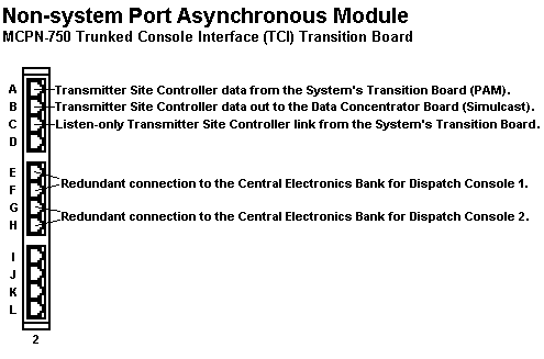
| Front panel elements of the PAM Board: | |
|---|---|
| Color | Description |
| Connector Port A | TCI to CSC link for console connection. |
| Connector Port B | TCI to RSC link for console connection. |
| Connector Port C | TCI to CSC link for console connection. |
| Connector Port D | No connection |
| Connector Port E | Output for TIMI link to CEB for dispatch console. |
| Connector Port F | Output for TIMI link to CEB for dispatch console. |
| Connector Port G | Output for TIMI link to CEB for dispatch console. |
| Connector Port H | Output for TIMI link to CEB for dispatch console. |
| Connector Port I | No connection |
| Connector Port J | No connection |
| Connector Port K | No connection |
| Connector Port L | No connection |
The RIC card connects to the rear of the backplane opposite an ACE board. It provides one port for connections to each of the possible seven base station repeaters. In a redundant controller configuration, these ports connect to the T-Bar Switch, which in turn connects to the base station repeaters.
| The I/O ports of the RIC (Repeater Interface Card): | |
|---|---|
| Color | Description |
| Channel 1 | Output to base station repeater. In redundant controller configuration, output connects to the T-Bar Switch. |
| Channel 2 | Output to base station repeater. In redundant controller configuration, output connects to the T-Bar Switch. |
| Channel 3 | Output to base station repeater. In redundant controller configuration, output connects to the T-Bar Switch. |
| Channel 4 | Output to base station repeater. In redundant controller configuration, output connects to the T-Bar Switch. |
| Channel 5 | Output to base station repeater. In redundant controller configuration, output connects to the T-Bar Switch. |
| Channel 6 | Output to base station repeater. In redundant controller configuration, output connects to the T-Bar Switch. |
| Channel 7 | Output to base station repeater. In redundant controller configuration, output connects to the T-Bar Switch. |
| CLK TX | No connection. |
| TDATA | No connection. |
| SER 1 | TSC link that supports the flow of control information between the CSC function of the MCP-75O System Board and the Transmitter Site Controller (TSC) function on the ACE-1 board. |
| SER 2 | RSC link that supports the flow of control information between the CSC function of the MCP-75O System Board and the Receiver Site Controller (RSC) function on the ACE-1 board. |
| ALARMS | Output to customer alarm system. |
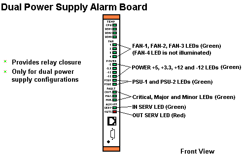
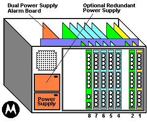
The Dual Power Supply Alarm board provides relay closures to alert you if one of the power supplies fails.
The alarm board is only available for systems that use the optional dual power supply configuration. For systems with only one power supply, the loss of power results in a major alarm.
Normally, the redundant power supply splits the power load. If one power supply becomes inoperable, the other one assumes the full load with no down time.
IMPORTANT: Do not connect both power supplies to the same circuit or circuit breaker. Link Status Board - Front Panel
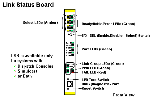
| Link Status Board - Front Panel: | ||
|---|---|---|
| LED or Switch | Color | Description |
| Ready/Dsbl/Error LEDs (1-7) |
Green | A solid green Ready/Dsbl/Error light indicates that the selected TCI link is enabled. An extinguished Ready/Dsbl/Error light indicates that the selected TCI link is disabled. A flashing green Ready/Dsbl/Error light indicates that the selected TCI link is malfunctioning. |
| Select LEDs (1-7) |
Amber | Indicates that the TCI link is selected to be either enabled or disabled. |
| E/D - SEL switch | - | Allows you to select a TCI link by pressing down on the switch repeatedly until the desired link's amber Select LED illuminates. For the selected link, you can toggle between Enable and Disable by pressing up on the switch. Disabling a T-link with this switch extinguishes the link's LED. |
| Port LEDs (SER 1, SER 2, TCI 1, TCI 2, TCI 3, TCI 4) | Green | Indicates the functional status of the SER 2 port on the LSB RIC repeatedly until the desired link's amber Select LED illuminates. For the selected link, you can toggle between Enable and Disable by pressing up on the switch. Disabling a TCI link with this switch extinguishes the link's LED. |
| Link Group LEDs (TCI 1-4) | Green | Indicates that you are selecting TCI ports 1-4 using the E/D-SEL switch. |
| PWR LED | Green | Indicates that the link status board is on. In a redundant controller configuration, the PWR LED is the only LED lit on the idle controller. |
| FAIL LED | Red | A flashing FAIL LED indicates that one of the TCI links is malfunctioning (or one of the DCB links if you have a Simulcast system). |
| LED Test switch | - | Initiates a self-test of all LEDs to determine if any LEDs have failed. This test does not use the processor to illuminate the LEDs. It is a hardware test only and does not affect the board's operation. |
| Diagnostic (DIAG) port | - | Provides an RS-232 port for reporting the status of all the links connected to the board, the version number of the board software, and the baud rates for the TCI board (and the DCB board if you have a Simulcast system). |
| Reset switch | - | Resets the Link Status Board (LSB). |
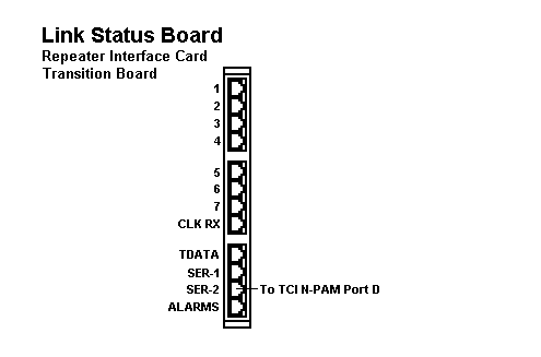
| Description of LSB RIC I/O Ports: | |
|---|---|
| Port | Description |
| Channel 1 | No connection. |
| Channel 2 | No connection. |
| Channel 3 | No connection. |
| Channel 4 | No connection. |
| Channel 5 | No connection. |
| Channel 6 | No connection. |
| Channel 7 | No connection. |
| CLK RX | No connection. |
| TDATA | No connection. |
| SER 1 | No connection. |
| SER 2 | Connection to TCI N-PAM Port D. |
| ALARMS | No connection. |
| On/Standby Power Switch: | |
|---|---|
| If the MTC-3600 does not power up: | Verify that the LEDs on the power supplies are illuminated (green) to determine if the power is being provided to the chassis. |
| If the MTC-3600 does not assign a control channel within 5 minutes: | Ensure that the base station repeaters are powered up. |
Normal Power up LED patterns MCP-75O
The following sequence describes the LED patterns for the MCP-75O system board during the normal operating state and power up.
The LEDs indicate the normal operating state as follows:
Normal Power up LED patterns ACE-1
The following sequence describes the LED patterns for the ACE-1 board during the normal operating state and power up.
The following sequence shows the LED patterns for the ACE-1 board during power up. ACE boards 2-4 have a similar LED pattern, but no control channel is assigned.
The LEDs indicate the normal idle operating state as follows:
The following sequence shows the LED patterns for the ACE-1 board during power up of the idle controller in a redundant configuration.
The following sequence shows the LED patterns for the MCPN-75O during normal operation state and during power up.
If all of the above conditions are met, you may need to replace the board on which the LEDs failed to illuminate.
If the LEDs on one board fail to illuminate properly. You may need to replace the board on which the LEDs failed to illuminate.
Verifying Factory Settings:
The Motorola factory sets the three DIP switches on the ACE-1 board. Two DIP switches are for the baud rate of the TSC and RSC links; the third DIP switch is for the base station repeater type.
Result: The ACE-1 board startup banner appears:
| ACE-1 Board Startup Banner Line Information: (refer to the listing above) | ||
|---|---|---|
| Line Number |
Name | Description |
| 1 | - | Motorola copyright banner message |
| 2 | - | Blank |
| 3 | Function | Indicates the major function of this board. All systems will contain one and only one ACE-1 board. Optional subordinate ACE boards are used to support channels 8-14, 15-21, and 22-28. |
| 4 | Site Configuration |
Indicates the site configuration in which this ACE board is being used. Display possibilities include the following:
|
| 5 | SW Revision | Indicates the software revision number of the ACE application. The software revision number of the Boot Loader program is available by logging into the ACE board and typing VERsion at the "ACE>" command prompt. |
| 6 | Station Type | Indicates the base station type used on the four control channels. Possibilities include the following:
|
| 7 | RSC Link | Indicates the baud rate selected for the RSC link serial interface to the CPU board. Possibilities include the following:
|
| 8 | TSC Link | Indicates the baud rate selected for the TSC link serial interface to the CPU board. Possibilities include the following:
|
| 9 | DIAG | Indicates the following:
|
| 10 | Connect Tone | Indicates the subscriber's connect tone frequency. Possibilities include the following:
|
| 11 | - | Indicates that the channels associated with the ACE-1 board have been tested and that the CPU board has indicated that the system configuration is either a "SmartNet" or "SmartZone" system. The active-idle state of the controller is also indicated. |
| 12-18 | - | Indicates that a state change has occurred for each channel listed. This is a normal consequence of the channel testing procedure at startup. The results of the test are indicated as follows: "Enab" (enabled), "Dsbl" (disabled), and "Malf" (malfunction), each followed by the channel number. The message is also displayed when an operator causes a state change either from the front panel SEL E/D switch or through a state change command from the SMT terminal. |
| 19-21 | - | Indicates the presence or absence of the three ACE subordinate boards. Also indicates that the ACE-1 board has disabled those channels normally handled by any of the missing ACE boards. If ACE board 2,3, or 4 is present, the indicated message is displayed regarding each board. |
| Supporting ACE Boards (ACE-2, 3, and 4) Startup Banner Line Information: | ||
|---|---|---|
| Line Number |
Name | Description |
| 1 | - | Copyright |
| 2 | - | Blank |
| 3 | Function | Indicates the function of the ACE board. Possible values are:
|
| 4 | Site Config | Indicates the site configuration. Possible values are:
|
| 5 | SW Revision | Indicates the software version stored in non-volatile memory. |
| 6 | - | Indicates that communication has been established between ACE-2 and ACE-1. |
| 7 | - | Indicates the ACE board has tested (TSTAT) and enabled the channels it manages. |
| 8 | - | Indicates the Connect Tone frequency for the channels managed by the ACE board. |
| 9 | - | Indicates:
|
| 10-16 | - | Indicates that a state change has occurred for each channel listed. This is a normal consequence of the channel testing procedure at startup. The results of the test are indicated as follows: "Enab" (enabled), "Dsbl" (disabled), and 'Malf' (malfunction), each followed by the channel number. The message is also displayed when an operator causes a state change either from the front panel SEL E/D switch or through a state change command from the SMT terminal. |
Removing the ACE-1 Board and manually set the DIP switches.
| Manually Setting ACE-1 Board DIP Switches: | |
|---|---|
| 1 | Attach an Electrostatic Discharge (ESD) strap to your wrist. Attach the other end of the ESD strap to the chassis as a ground. The ESD strap must be secured to your wrist and be grounded throughout this procedure. |
| 2 | Shut down the operating system:
|
| 3 | To remove the ACE-1 board, use a #1 Phillips screwdriver to loosen the screws, which are partially hidden by the ejector handles. Release the top and bottom ejector handles and slowly slide the board out of the slot. IMPORTANT: Avoid touching areas of integrated circuitry. Static discharge can damage these circuits. |
| 4 | Set the Repeater Type DIP switches on the ACE-1 board according to the Repeater Type Settings table. |
| 5 | Set the Serial A and Serial B Baud Rate switches according to the Baud Rate Settings table |
| 6 | Carefully slide the ACE-1 board back into the slot. Grasping the top and bottom ejector handles, be sure the module is well seated in the P1 through P5 connectors on the backplane. Be careful not to bend the connector pins. |
| 7 | Secure the ACE-1 board in the chassis with the screws provided, making good contact with the transverse mounting rails to minimize RE emissions. |
| 8 | Start the MTC-3600 controller.
|
Factory Squelch Settings
The factory squelch setting is 0 (zero). This is also the default as stored in Settings nonvolatile memory. Zero represents the minimum possible squelch setting, which is wide open (the UNSQ LED is constantly illuminated). For proper system performance, adjust the squelch setting for your system as shown in the following procedure. The valid range is from 1 to 127.
Important: Setting squelch too high or too low causes abnormal operation. For example, if you set squelch too high, you may not be able to access the system. If you set squelch too low, the controller may try to use random noise as data, resulting in error messages. Both cases will result in degraded system performance.
| Manual squelch setting: | |
|---|---|
| 1 | Wait for the ACE-1 board startup banner to appear and a control channel to be assigned. Then using the ACE Diagnostic Interface, press 'Enter'. Result: A logon prompt appears. |
| 2 | At the login prompt, type control and press 'Enter'. Result: The Enter Password prompt appears. |
| 3 | Type trunking and then press 'Enter'. Result: The "ACE>" prompt appears. |
| 4 | Type sqlh and then press 'Enter'. Result: The current squelch value appears, followed by the following prompt: Change (Y/N/+/..)? |
| 5 | Type Y and then press 'Enter'. Result: The Enter New Squelch Value prompt appears. |
| 6 | Set the squelch value by typing + to increment by one value. Continue typing + until you reach the value where the squelch LED is extinguished. You can type - to decrement by one value, if necessary. You can also enter a numerical value for the squelch setting by typing Y then pressing 'Enter' Result: The UNSQ LED flickers then extinguishes if the setting is connect. Once the value is set, it is maintained in nonvolatile memory. |
| 7 | Confirm the correct setting by using a radio to place a call. Result: The UNSQ LED illuminates briefly, then the DECD LED illuminates briefly. Finally the radio channel is assigned. |
| 8 | If you have two to four repeaters that can act as the control channel, disable the current control channel and repeat this procedure for all remaining control channels. Use the lowest squelch value to ensure proper operation across all control channel repeaters. |
Manually Enabling and Disabling Channels
The channels can be enabled and disabled to force the use of an single control channel and voice channel in order to test a certain channel for voice communications. Trunked systems will have 1-28 channels.
The following procedure will enable and disable channels using the E/D-SEL switch on the ACE boards.
NOTE: You cannot use the E/D-SEL switch to select un-configured channels or channels disabled by the System Manager Terminal (SMT) interface.
Emulated MC-6809 Components Single site SmartNet trunked system table below shows the components of a MC-6809 trunked system. The second table shows the MC-6809 system with telephone interconnect and Centracom console interface.
Basic Standalone MC-6809 SmartNet Trunked System
MC-6809 Component
CSC - Central Site Controller
RSC - Receiver Site Controller
RIB - Receiver Interface Board
IRB - Inbound Recovery Board
TSC - Transmitter Site Controller
TIB - Transmitter Interface Board
Standalone MC-6809 SmartNet Trunked System
with Centracom Console Interface and Central Telephone Interconnect
MC-6809 Component
CSC - Central Site Controller
TCI - Trunked Console Interface
ACB - Asynchronous Communications Board
RSC - Receiver Site Controller
RIB - Receiver Interface Board
IRB - Inbound Recovery Board
TSC - Transmitter Site Controller
TIB - Transmitter Interface Board
Central Interconnect Terminal
PLIB - Phone Line Interface Board
Matrix - Matrix Board
TRIB - Telephone Repeater Interface Board
MCD - Master Control Board
COMPARISON OF MC-6809 COMPONENTS TO MTC 3609 COMPONENTS
Emulated MC-6809 Components
Single site SmartNet trunked system including both with Centracom Console interface and Central Telephone Interconnect. The table below compares the components of a MC-6809 trunked system with the analogous MTC-3600 component.
MC-6809 Central Controller vs. MTC-3600 Functionality with CIT
MC-6809 Component
MTC-3600 Component
CSC Central Site Controller
MCP750 System Board
RSC - Receiver Site Controller
ACE-1 Board
RIB - Receiver Interface Board
ACE-1 through ACE-4 Boards
IRB - Inbound Recovery Board
ACE-1 Board
TSC - Transmitter Site Controller
ACE-1 Board
TIB - Transmitter Interface Board
ACE-1 through ACE-4 Boards
Central Interconnect Terminal
Central Interconnect Terminal
PLIB - Phone Line Interface Board
PLIB - Phone Line Interface Board
Matrix - Matrix Board
Matrix - Matrix Board
TRIB - Telephone Repeater Interface Board
TRIB - Telephone Repeater Interface Board
MCD - Master Control Board
MCD - Master Control Board
MC-6809 Central Controller Vs MTC-3600 Functionality - with CIT and Centracom Console
MC-6809 Central Controller
MTC-3600 Functionality
CSC - Central Site Controller
MCP-75O Systems Board
TCI - Trunked Console Interface
MCP-75O Systems Board and N-PAM Board
ACB - Asynchronous Communications Board
(nil)
RSC - Receiver Site Controller
ACE-1 Board
RIB - Receiver Interface Board
ACE-1 through ACE-4 Boards
IRB - Inbound Recovery Board
ACE-1 Board
TSC - Transmitter Site Controller
ACE-1 Board
TIB - Transmitter Interface Board
ACE-1 through ACE-4 Board