
The hard disk drive is one of those devices that has a good excuse if it suffers from a complex. Of all the devices in the system, the hard drive has seen as rapid and dramatic a pace of improvement as any other, including the CPU. Yet it never gets the fanfare. It does more physical work than any other component, and yet the user complains when it makes too much noise.
From the time the Winchester Hard Disk Drive was introduced in 1975 to the present, experienced computer users have considered a hard disk drive a necessity. A hard drive is the fundamental form of mass storage in use today. While all systems of today ship with one installed, this has not always been the case. Most early computers, such as the Timex Sinclair, the Commodore series of computers, and Radio Shack's TRS-80s used a tape drive for storage. Even after the release of the PC, hard disks remained an option (and an expensive one at that) for many years.
The Winchester was far from being the first hard disk, however. IBM developed the first true hard disk drive in 1956. It called it the 305 RAMAC. The letters stood for Random Access Method for Accounting and Control. It possessed fifty disks that were two feet in diameter, and stored a mind-boggling five megabytes of data.
To help you understand hard drives, I'll be taking you though a few other parts of the computer as well. I'll be discussing certain BIOS instructions as well as hard drive geometry. A key issue that impinges heavily on computer performance is how a particular computer deals with I/O operations.
Every hard drive in use today traces its ancestry back to a form of design based on the CHS parameters. CHS stands for Cylinders, Heads, and Sectors per track. It is through this configuration that the system determines the storage capacity of the drive, and it is through this geometry that the file allocation table is able to properly map the information stored on the device. IBM first introduced CHS on the IBM PC.
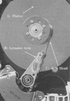
 I discussed the concepts of sectors and tracks on the web page Working with Removable Disks. With hard drives comes a new geometric structure. Hard drives also have cylinders. Hard drives are generally equipped with more than one disk onto which data is stored. These are called platters. On most hard drives, each platter also has two surfaces on which data is stored. (Some of the less expensive models save a few dollars per drive in production costs by not equipping the bottom surface of the platter closest to the drive's base with an actuator arm and R/W head.) If you take every track that is vertically aligned across every surface of each platter, you have a cylinder. The figure shows you the relationships between sectors, tracks, and cylinders.
CHS reads are initialized by a routine in the BIOS known as Intl3H. INT stands for interrupt and 13h is simply the hexadecimal for the number 19. Therefore, you could simply call it Interrupt 19, and you would be still correct. The Intl3h routine provides for a three-dimensional address space. This space allocates a 10-bit address for tracking cylinders, an 8-bit address for heads, and a 6bit address for sectors per track. As a result, Intl3h supports 1024 cylinders, 256 heads, and 63 sectors per track. All hard drive calls must, in some way, shape, or form, conform to these parameters.
Herein lies the problem. If you do the math, you'll see that Int13h is limited to reading 16,515,072 sectors. Multiply that by 512 for the number of bytes in a sector and you see that Intl 3h provides support for hard drives up to and including 8GB hard disk drives. That's all, folks.
Now, obviously there are much bigger drives than this. Most computers shipping today have drives in the 40-80GB range. These larger drives are made possible through one of the drive translation methods that I will discuss later in this chapter. Drive translation takes disk space beyond what Intl 3h would typically be able to read and converts those locations into something it does understand. This is made possible by adding the Intl3h extensions to the BIOS.
So why not just get rid of the Intl3h altogether and replace it with something more modern and up to date? The problem there is that it isn't just hardware that addresses this interrupt. Any software that wants to read to the disk, which is any software written in the past twenty-five years or so, also addresses the Intl 3h call. If Intl 3h suddenly disappears, none of that software will work. For some reason people get upset when they find the new computer they just bought won't run several thousand dollars' worth of software they've bought over the past few years.
To make sure this didn't happen; engineers simply added the extensions. Hardware and software make their calls to the to Intl 3h. The extensions intercept these calls and engage whatever drive translation method has been chosen. Newer extensions replace the 24-bit address space of Intl 3h with a 64-bit space. As a result, drives in the nine and a half trillion-gigabyte range are theoretically possible.
The long and short of it is that, no matter what kind of hard drive you have, it needs to be able to somehow translate all I/O operations into something that the antiquated concept of Intl 3h can comprehend. When data is requested from the hard drive, the controller will first locate the cylinder that holds the data. Then it will determine which specific track has the data so that the correct R/W head is activated. Once the track is located it will lock on to the first sector that holds the data the system needs.
Early hard drives also were afflicted by the requirement that each track has the same number of sectors, regardless of their position on the platter. The tracks toward the spindle had no fewer sectors than the outermost track. As a result, the tracks toward the outside consisted of wide, sweeping sectors, while the ones toward the inside were all bunched together. Western Digital developed a technology called zone bit recording that allowed the sectors to be approximately the same size. The outside tracks could contain a greater number of sectors than those near the spindle. This is illustrated in the figure to the right.
The physical structure of the hard drive makes it one of the most complicated devices in your system. It is an electromechanical device that requires a large number of moving parts and a fair amount of logic circuitry to work. While the platters and read/write heads are the core of the hard drive, there is a lot going on that makes them work together. And, as with any other chain, the whole thing falls apart at the weakest link.
The flat disks onto which data is stored are the platters. These consist of a rigid substrate material coated with some form of magnetic medium. Aluminum is the most common metal used for the substrate, although there are some companies who have taken to using glass. The platters must be very light and very rigid. Also, the surface of a hard disk must be machined to extremely tight tolerances, and aluminum is one of the easiest metals to work with. The magnetic medium has gone through a few changes over the years.
The magnetic medium is what actually holds the information you store on your drive. Zeros and ones are registered simply by the amount of magnetic charge stored by the magnetic particles. In a way, ours is an industry of sand and rust. The first material used was ferrous oxide, or plain old rust. Admittedly it was very refined rust, but when all the fancy terms are put aside, rust it was. Into the ferrous oxide was mixed an adhesive material, and it was applied to the platter using a spin-coating method. While the disk was rapidly spinning on a platter, the medium was applied. What managed to stick in spite of the forces of inertia was an incredibly even and extremely thin layer of the material.
Metal oxides had their problems though. The particles were somewhat large and didn't provide as smooth a surface as might be desirable. Read/write heads had to be positioned farther away in order to prevent impact with particles that might protrude slightly from the surface. The size of the particles meant that there could only be so many per square inch. This limited how much data could be stored on any given platter.
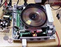
 Newer drives, like the one shown, use thin-film metal media. This allows for greater storage capacities and a thinner surface. A thinner surface allows read/write heads to float closer to the surface. Between the refined media and this closer proximity less magnetic energy is required to magnetize the particle.
Thin-film media is also more efficient for the manufacturers. The material is applied to the platter in a process called vapor deposition. This process vaporizes the metal in a chamber. The aluminum platter attracts the molecules of the metal vapors until the surface has all it can hold. The end result is the thinnest and most uniform coating that, until recently, technology was able to offer.
Prior to selling its hard drive division to Hitachi, IBM developed a technology using glass platters instead of aluminum. It claims that glass allows for higher information density and tighter head-to-surface tolerances. IBM's designers must be onto something. One of their first releases was a tiny drive that housed 1.7GB of data per square inch.
It wasn't just the substance of the platter they changed. They also came up with a new technology for platter coatings. This new surface promises a surface that is far more uniform and holds up to a hundred times more data per square inch than conventional materials. To do this, they heat a mixture of iron and platinum. When deposited on the platter the mixture forms a nearly perfect matrix of submicroscopic crystals. These crystals are much smaller than the clusters of molecules conventional magnetic media requires to hold a single bit, and each crystal can store a bit.
Now that you have a surface on which to store your data, you need a way to put that data on and get it back off. For every advance in coating technology, there has to be a corresponding advance in read/write (R/W) heads. Their job is to take bits of information from the computer and convert them into magnetic pulses, which in turn magnetize the surface of the medium. When the computer asks for information to be returned, they have to read the magnetic patterns embedded on the platter and convert that energy into digital information.
The term read/write is actually a misnomer on modern hard drives. In the old days, a single head performed both read and write operations. Those days are long gone. Current drives have one transducer that handles write operations and another that reads data back. They are assembled into a composite assembly that is so small as to look like a single unit to the naked eye.
One of the problems that designers face in the rapidly advancing technologies of hard drives is that, the more data that gets packed onto the drive, the smaller the individual bit cells become. A bit cell is the tiny collection of magnetic particles that house a single bit. The size of the bit cell will determine the track width. As tracks become narrower, the R/W heads must focus on a correspondingly smaller target.
Also, as the bit cells become smaller, they form tighter clusters with much less distance between cells. It is rather important that the magnetic energy of one bit cell not interfere with that of its neighbor. To prevent this, modern drives put a substantially weaker charge into each bit cell. An amplifier boosts that signal to a level that the controller can convert into digital signals.
For each surface of a disk platter that stores information, there must be an R/W head. When I get to the section that discusses how data is actually located on a drive I will discuss a situation where an extra head is employed. But for now, I'll stick to the one surface/one head scheme.
A critical issue relating to R/W heads is their floating height. In operation, the head does not actually come in contact with the platter. It floats on a cushion of air just a few nanometers above the surface of the platter. That distance is called the floating height. To put this in perspective, if the head were the size of an average two-story house that floated above the ground (and just try getting that to happen!), you wouldn't be able to slip a sheet of paper between the house and the ground.
In fact, in the event that the head and platter should come in contact with one another, this results in the infamous head crash. Head crashes are disastrous in that not only is the medium damaged; the head, and therefore the hard drive, will almost certainly be destroyed. There are two things that can cause a head crash. The most common is the irate user kicking a misbehaving computer. The impact of foot against computer while the disk is spinning kills the drive. A more uncommon cause is a piece of foreign material that somehow makes its way into the drive. Modern drives are so well sealed that this is an extremely rare event.
R/W heads can't move themselves across the platter. They've got to ride on something, and that is the job of the actuator arm. As I've pointed out, each platter has two surfaces, and each surface needs its own R/W head. If you look at an open drive, you will see how all the actuator arms are mounted in as a group. All platters are mounted to the same spindle. There is one pair of arms associated with each platter. When the controller needs to locate information on a different track, it directs the actuator arms to move the heads to that track.
In the old days, the same type of stepper motor I described in Chapter Twelve was used to control the actuator arms. Newer hard drives use a voice coil mechanism. This consists of a magnetic coil that moves the arm in a distance proportionate to how much energy is applied to the coil. It gets its name from the fact that this is the same technology that moves the diaphragm of a loudspeaker in a stereo system. The advantage of a voice coil mechanism is that it is more accurate and has few moving parts. Therefore, not only does it work better, it lasts longer.
A key reason manufacturers made the change from stepper motors to voice coils was because of how much data gets packed onto today's hard drives. I discussed earlier about the sectors on a hard drive being laid out in tracks. How much data can be squeezed onto a drive is directly related to the number of tracks per inch (TPI) the manufacturer can fit onto an individual platter. The first hard drives had only a couple of hundred TPI. Modern drives have now exceeded 28,000 TPI. Accurately positioning an R/W head over tracks that small would be impractical using a stepper motor.
The voice coil has no rigid steps over which it must move. Also, by providing some form of feedback mechanism, if the first attempt to position the head turns out to be inaccurate, a device called the servo dynamically repositions it in just a few milliseconds.
Earlier, I mentioned that the head floats on a microscopically thin layer of air above the spinning platter. I pointed out that if the head should come into contact with the platter, it would cause a head crash.
When you turn your PC off, and the platter stops spinning, that head is going to sit down: on the platter no matter what you do. Manufacturers have accordingly created a head parking system, designing into the drive platters an area reserved solely for the purpose of providing the head a safe place to sit when the PC is not in operation. This is the landing zone. The location of the landing zone is one of the hard disk configuration settings of the BIOS. However, all modern hard drives are designed in such a way that the BIOS can automatically detect the necessary parameters.
In the early days of computer technology, it was up to the user to properly park the heads when the PC was powered down. MS-DOS had a head-parking utility just for that purpose. Fortunately for us, it has been many years since that's been necessary. Hard drives now automatically park themselves as part of their shutdown procedure. This is good, but IBM's approach is better.
It uses a process called load/unload. When a power-down is in process, the heads are lifted into the air. Instead of dropping the heads onto the surface of the platter, IBM drives slide the actuator arms onto a restraining mechanism, which prevents the heads from ever coming into contact with the platter.
Manufacturers provide all kinds of specifications to show you just how fast their drives are and why they are so much better than the competition's. The specifications provided are indeed very valuable bits of information to use when selecting a drive. I will discuss in detail the most commonly advertised specs in detail. A important limitation of hard drive performance that is rarely, if ever, mentioned by hard drive manufacturers is the amount of time required to actually perform an I/O operation from beginning to end. But since I/O operations per second are a direct corollary of the basic specifications, I'll discuss those first.
The easiest way to improve a hard drive's overall performance is to make it spin faster. In the next two sections I will be discussing the factors of latency and data transfer rate. Both of these are directly affected by how fast the disk is spinning.
Early disks spun at 4800rpm. However, recent technologies have pushed the limit to an amazing 15,000rpm. To put that in perspective, let's go back to the analogy of the R/W head being the size of a two-story house. I also said that if it were that large, the floating height was so minute, you wouldn't be able to fit a sheet of paper between the house and the ground. Now factor this into the equation. At 10,000rpm, the ground is moving beneath the house at a speed the equivalent of approximately 6000 miles per second!
Which brings us to one of the problems design engineers had to face when designing drives this fast. It is critical that the surface be as absolutely smooth as possible. Also, significantly more heat is generated by these drives, both from the more powerful motor and from friction, which needs to be dissipated. This is something that you need to consider when designing a system for yourself or a client. If you wish to use one of these faster drives, efficient cooling of the case isn't just an option. It's an absolute necessity. This is further exacerbated when several of these drives are used together for a drive array.
The impact of rotational speed on performance is rather critical. The faster a disk rotates, the faster the R/W heads can latch onto the first sector of data during a seek operation. Once data begins to be read from the surface of the disk, faster rotational speeds mean that data is moving beneath the heads that much faster. Therefore data transfer rates are improved as well.
Frequently, manufacturers will advertise their average seek time. This is all fine and good, and it's a wonderful thing to know. However, average seek time is only half of the equation that yields average access time. Average access time is the time that elapses between a request for data and the instant that the first bit in information is picked up by the R/W head. The other half of the equation is the drive's latency.
Average seek time is a guess at how long it will take to move the R/W heads into position to lock onto the correct track. When the manufacturers make these measurements, they are based on moving the heads a distance equal to one third of the diameter of the platter. Obviously, if the actuator arm has to move from the first track to the last, this time will be longer. Conversely, if it is only moving from track one to track five, it will be much shorter. Still, this average provides a good comparison between two competing drives.
Latency is how long it takes for the R/W heads to lock onto the sector once the track has been located. This specification is calculated by taking rotational speed and calculating how much time one half of a complete rotation will take. Therefore a hard drive with a rotational speed of lO,000rpm will have a published latency of three milliseconds.
Of course, this is an inaccurate assessment of reality. Should the actuator arm lock onto the track a fraction of a rotation before the sector shoots past in its rotational path, it won't have time to lock onto the sector on that rotation. In effect, it would take in excess of a full rotation to actually locate the sector. The table compares rotational speed to latency.
| Average latency measurements based on rotational speed |
| Rotational Speed (rpm) | Rotations/sec | Milliseconds/rotation | Latency |
| 15,000 | 250 | 4ms | 2ms |
| 10,000 | 166.666 | 6ms | 3ms |
| 7,200 | 120 | 8.33ms | 4.16ms |
| 5,400 | 90 | 11.111ms | 5.555ms |
| 4,800 | 80 | 12.5ms | 6.25ms |
The impact of rotational speed is seen both in how many tracks per second
can be read and in how long it takes to complete a single rotation. |
Once the data has been located and begins to move from the surface of the platter, across the drive electronics, and finally into memory, the concept of data transfer rate (DTR) comes into play. As I mentioned earlier, this is directly affected by the rotational speed of the drive.
Unfortunately for the world of consumers, there are several different methods by which DTR is measured. Most commonly cited is burst mode. This is how fast data can move from the R/W head to the drive's buffer in a perfect world when the data is moving downhill with a tail wind. In other words, you're never going to see those speeds. You might see this listed as the internal host transfer rate as well. The external host transfer rate is a far more critical measurement, because this tells you how fast data gets moved from the controller to RAM.
Transfer rates are provided in megabytes per second (MB/s) ratings. In the next chapter, as I discuss the different interfaces hard drive use, I'll take a closer look at some of these ratings.
Hard disk I/O operations result in one of the biggest bottlenecks of system performance, simply because of their complexity and how often they occur. When data that does not exist in memory is requested by the CPU, a very convoluted process begins in order to locate that data on the hard drive and transfer it to memory where it can be used. There are actually four steps to a hard drive I/O operation.
- The Queuing Phase: This is where all the commands required by the hard disk controller are issued and, when possible, lined up in the correct order for execution.
- The Command Phase: The commands are executed in the order in which they exist in the controller's cache memory.
- The Access Phase: The R/W heads locate and lock on to the first sector containing the requested data.
- The Data Transfer Phase: Data is copied from the surface of the drive, moved to the controller's cache RAM, and then to system RAM.
After reading the previous section, it should be obvious that the number of clock cycles for a single I/O operation can be quite substantial. And remember that transferring even a small file may result in multiple I/O operations. When files get fragmented on the hard disk, they require multiple I/O operations. This is the key reason a badly fragmented disk hurts system performance so badly. The table summarizes I/O operations, providing a crude estimate of how long transferring a single burst of data can actually take.
| Estimating I/O Operations Per Second of a typical 7200rpm hard drive |
| I/O Phase | Est. Time (ms) | Est. Time (cc)1 | Total CC Elapsed |
| Queuing Phase | 30 to lO,0002 | 30,000 to 10,000,000 | 30,000 to 10,000,000 |
| Command Phase | .001 to .003 | 1 to 3 | 30,001 to 10,000,003 |
| Access Phase3 | 14.2ms | 14,200 | 44,201 to 10,014,203 |
| 1CC clock cycles: based on a 100MHz front-side bus. 2Time required for the queuing phase is dependant on the number of commands required to perform a specific I/O request. 3Access phase is one of the few delays you�ll see published in the manufacturer�s specs as average access time. |
The data that is stored on your hard drive isn't really data at all. You can't put a hard drive platter under a microscope and read off the zeros and ones stored there. The information is encoded into patterns of magnetically charged particles. The controller coverts a digital signal into electronic pulses which, in turn, magnetize the metal or metal-oxide particles on the platter. When the heads read data back, it is their task to interpret the pattern of charged particles and convert the magnetic fluxes into an electrical signal the controller can turn back into data. This is all part of the data encoding mechanism. All devices need some encoding mechanism.
Binary data moves across the bus as positive and negative electrical charges. Moving from a positive to a negative state is known as a flux reversal. The hard drive has a chip on board known as the encoder-decoder (ENDEC) that has the job of taking these digital waveforms and converting them into electrical signals that get sent to the R/W heads. The heads apply the magnetic charges to the media surface. A single bit of data requires tens of thousands of molecules of media to create one of the bit cells discussed earlier
One of the limiting factors that determine the maximum capacity of a hard drive is how many times it is possible to change the magnetic polarity of individual particles in a square inch of drive surface. If the polarity changes overlap, they will impact on one another. Try this little experiment. Take two magnets and some iron filings. Sprinkle the iron filings onto a sheet of paper and put one of the magnets underneath the paper and watch the pattern that the filings assume. I'm sure you did this in grade school at some time or the other. Now take the other magnet and place it alongside the first magnet under the paper. Watch what happens to the filings. Rotate one of the magnets 180 degrees and see how this affects your little patterns. The closer you move the magnets to one another, the greater the confusion.
This is pretty close to what is going on when the R/W heads apply flux reversals to the media surface, except on a submicroscopic level. If the charged particles are too close to one another, the integrity of your data can be affected.
Another thing that can impact data integrity is the synchronization between the read heads and the write heads. In order to make sure that data is read back in exactly the same way as it was recorded, an accurate timing mechanism must be employed to assure synchronization. Then all read and write heads on the drive march to that same beat.
As data is written to the drive, it goes down in a series of electrical pulses that create transition cells. A transition cell is the minimum number of particles that can be affected by a single magnetic flux. Now if all data alternated evenly between zeros (-) and ones (+), then on playback, the data would look like -+-+-+-+-+ and there would be no issues. However, that would be like having a dictionary that read ABABABABABABAB from beginning to end. It wouldn't be interesting, informative, or accurate. In other words, it would be useless.
Real data will have varying numbers of zeros and ones clumped together. Therefore, the R/W head will encounter varying amounts of time in which is sees nothing but negative polarity, followed by equally varying amounts of time in which it sees nothing but positive polarity. Without a clocking mechanism in place it would appear to the controller as a -+-+-+ pattern, except that individual bits would take up widely varying amounts of hard drive space.
 The clock ticks off read/write intervals. If eight zeros in a row come down the pipe, the clock counts off eight transition cells for the write head to mark down. When the read head comes along to read that data back, the clock will tick though the transition cells, and the read head will find eight zeros. It is critical that clock mechanisms be incredibly accurate. If, for any reason, the read heads were out of synch with the write heads, the results would be disastrous. The figure shows you what would happen. The arrows represent individual ticks of the clock. The square waves in the top half of the diagram represent positive and negative magnetic pulses. Since this is an analog electrical event, a timing mechanism needs to be in place to assure that consecutive identical bits are properly read. In order to have the system accurately interpret the magnetized surface as encoded data, read and write operations must be synchronized. If the clock ticks off four cycles while applying a negative pulse (rendering four zeros), and on the read cycle, it ticks off five cycles (rendering five zeros) all the data from that point forward will be corrupt.
The encoding mechanism determines how binary data is converted into charged particles, and then when read back, how the charged particles tell the controller to create a binary signal. The two encoding mechanisms used over the years have been modified frequency modulation (MFM) and run length limited (RLL).
MFM was one of the first methods of data encoding used in hard disk drives. An earlier method of simple frequency modulation continues to be used on floppy drives, but has never been used on hard drives. Using simple frequency modulation, each bit of data stored on the drive is generated by an individual flux reversal. A graphics image that sent 5000 ones in a row would send across 5000 flux reversals. For each bit, a separate clock transition would be recorded along with the bit of data.
MFM minimized the usage of clock transitions by only requiring one when a zero was preceded by another zero. That reduced the amount of physical space on the platter that was being used by timing information, and made more room available for data. Since less timing data was being generated, the clock frequency could be doubled. In other words, twice as many bits of data could be stored to surface medium per flux transition.
Many books on the subject include MFM as a form of interface. This is not entirely inaccurate, nor is it entirely accurate. MFM is an encoding mechanism, not an interface. However, it requires its own separate interface. The controller that reads and writes data based on MFM encoding will work with no other device. Therefore, the MFM controller could effectively be considered to be the MFM interface.
RLL encoding is a far more efficient means of encoding large amounts of data. Because of this, it is the method used by virtually all hard drives manufactured over the course of about twenty years. Instead of encoding and decoding data a bit at a time, it takes a cluster of data and encodes it all at once. A single flux transition can write a large block of data.
Two parameters are used to define RLL sequences. Those are run length and run limit. A run is simply the number of clock cycles (of the hard drive's controller) that data can be written to the drive without a flux reversal. The run limit represents the maximum number of bits the controller would allow to be written in a single flux without embedding a clock signal. The run length is the actual number of bits written.
Since data is moved in blocks, rather than a bit at a time, the timing that I discussed earlier is easier to maintain. Also, since there are significantly fewer clock transitions that needed to be recorded, much greater data densities were made possible. All else being equal, an RLL drive can hold twice as much data as an MFM drive using exactly the same medium.
Even RLL imposed some severe limitations on the amount of data that could be stored on the hard drive. Recent disk drives have been manufactured using an encoding mechanism called partial response/maximum likelihood (PRML). PRML doesn't try to read every single flux reversal that occurs. Instead, it uses a very sophisticated digital sampling algorithm. The electrical signal that is generated by the reading of magnetic impulses on the surface of the drive is scanned and samples of that signal are taken at precisely timed intervals. This is the "partial response" half of the equation. The controller then calculates the most likely sequence of bits that would occur as a result of those samples. That is the maximum likelihood."
Doesn't sound very accurate, does it? The fact is, bit errors from this method are only one in every several trillion bits read. And because PRML permits up to thirty-five percent more storage capacity per platter (or areal density, as it's called) without changing the formulation of the medium, it is a logical choice for high-capacity drives.
Extended PRML (EPRML) works in exactly the same manner. However, improvements in the algorithms used and in the circuitry employed allow for faster write operations as well as faster reads. In addition it substantially increases area! density over that of PRML. This has been the method used for the last couple of generations of hard drives.
Now that I've discussed the basics of how information is stored on a magnetic disk, it is time to take a look at how the computer manages how it's stored. The writing of data is complex enough, but before the drive can read that data back later on down the road, there needs to be some way of locating that information. This is the function of the file system.
The file system is a direct function of the operating system. As such, the OS a user chooses affects many different functions of the computer system. Many of the functions impacted are under the control of the file system. For example, these days, most people take it for granted that they can name a file My Business Proposal.doc and every computer of every user who will access that document can read it. Most people don't even realize that prior to 1995, most operating systems would have returned a message along the lines of "invalid file name" if a user attempted to use such a name.
Most operating systems these days support multiple file systems. A problem that is occasionally encountered is that a file system supported by one OS may or may not be supported by another OS. Over a network, this isn't a problem. But it is something that must be considered if you are attempting to configure a computer to dual-boot. Dual-booting consists of installing two or more different operating systems and allowing the user to select which OS to use when he or she starts the machine.
For the most part, a discussion of file systems is more appropriate in a book on operating systems. I consider this to be an area of understanding that is critical to the hardware technician, though, and therefore am including it in this book. The file systems I will discuss in depth will be the File Allocation Table (FAT) system and New Technology File System (NTFS). Another file system not frequently seen today is High Performance File System (HPFS). Even though not as common, it is worth taking a brief look. Your CD-ROM drive uses its own file system known as Compact Disk File System (CDFS), which I will take a closer look at in Chapter Seventeen, Multimedia. Users of Linux and Unix make use of the Unix File System, which is completely incompatible with any of the FAT-based systems.
File Allocation Table, or FAT as I'll call it from here, was the original file system used by the first IBM-compatible PCs. It works by creating a database of entries that the operating system uses to find data on the hard drive. In fact, two different copies of that database are maintained. If you read some of the articles out of the popular press, you might think that there are only two versions of FAT: FAT16 and FAT32. You would, of course, be wrong. The first version of FAT was FAT12. The numbers represented in these different versions of FAT indicate how many bits are allocated to the binary number that identified individual clusters. In other words, FAT12 uses a 12-bit number, FAT16 makes use of a 16-bit number, and not surprisingly, FAT32 allows for a 32-bit number. Obviously, the more bits used to create the number, the more numbers the file system can generate. It also dictates cluster sizes and the maximum size of volume that was possible using a particular system. The table lists the various versions of FAT and how they differed.
| Comparison of FAT Systems |
| File System | Size of FAT Entry | Range of Cluster Sizes | Max Clusters | Max Volume Size |
| FAT12 | 12 bits | .5K to 4K | 4,086 | 16,736,256 bytes |
| FAT16 | 16 bits | 2K to 32K | 65,526 | 2,147,123,200 bytes |
| FAT32 | 28 bits1 | 4KB to 32KB | 268,435,456 | ~2 terabytes2 |
| 1While the actual entry for FAT32 is 32 bits, 4 bits are reserved for OS use and not used for generating cluster numbers. 2Roughly 2 terabytes is the theoretical limit to volume size in FAT32. However, limitations in the file allocation tables prevent drives from reaching this size under current technology. |
FAT12 has lived a long and healthy life as a file system. It continues to be used on floppy disks and on very small partitions. Both FAT16 and FAT32 have no trouble reading and writing to FAT12 partitions.
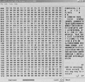 FAT16, for the longest time, was the file system of choice for nearly every computer in use. It allowed for partitions of up to 2GB, which at the time was considered to be unthinkably large. Four different primary partitions could be maintained on a single physical drive, allowing the user to create multiple logical drives or to install more than one OS on a single machine. If you were to open the FAT with a disk-editing tool (and I highly recommend you not do this unless you are either extremely capable, extremely careful not to edit anything, or have a strong desire to reformat your hard drive), you would see a list of every cluster on your hard drive, like the one shown. Of course, it wouldn't look much like a list to you, since it would consist of a bunch of binary code all run together. But each entry would contain certain information that allows the OS to find every cluster that hold data for that file.
This information includes the following:
- A designation whether the cluster is in use or not
- A point to the next cluster that contains data owned by that particular file
- A marker preventing it from being used if it has been marked bad
FAT16 is limited to a total of 512 entries in the root directory. This is due to a physical limitation of FAT16. The root directory has to start in the first sector immediately following the file allocation tables. Therefore, in order to make certain that the drive is efficiently used, the concept of directories was brought into play. As far as FAT is concerned, a directory is just another file. To allow the OS to distinguish between files and directories, FAT places a special marker in each directory. Directory entries contain information that directs the OS to the files or subdirectories that reside within it.
- 11 bytes identifying the name of the file or directory
- 8 bits defining the attributes of the file or directory
- 24 bits identifying the time the file was created
- 16 bits identifying the date the file was created
- 16 bits showing the last date on which the file was accessed
- 16 bits showing the time the file was last modified
- 16 bits showing the date the file was last modified
- 16 bits indicating the first cluster number occupied by the entry
- 32 bits indicating the size of the entry
I pointed out earlier that the hard drive's most basic element of storage is the sector. I also told you that hard drives no longer read single sectors, but rather file allocation units (FAUs) or clusters. FAT16 is not terribly efficient in its use of clusters. The larger the partition, the greater the number of sectors required to make a cluster. This is, of course, true of all file systems. It is simply more noticeable with FAT16.
The cluster is the smallest element into which the hard drive can actually store a file. As you can see, the smallest cluster used by FAT16 is 2K. What that means is that no matter how small a file might be, it will occupy a minimum of 2K of hard drive space. An example of this is the Windows icon. Those little pictures you see floating on your desktop are frequently less than 800 bytes. However, since they are individual files, each one of them eats up an entire 2K cluster. And the larger the partition, the more sectors, and therefore the more hard drive space you will need for individual files. The table details the cluster sizes used by FAT16 with the different partition sizes it supports.
| FAT16 File Allocation Unit Size by Partition Size |
| Partition Size | FAT Type | Cluster Size |
| 16MB to 128MB | 12-bit | 4 Sectors (Appx. 2K) |
| 128MB to 256MB | 16-bit | 8 Sectors (Appx. 4K) |
| 256K to 512K | 16-bit | 16 Sectors (Appx. 8K) |
| 512K to 1GB | 16-bit | 32 Sectors (Appx. 16K) |
| 1GB to 2GB | 16-bit | 64 Sectors (Appx. 32K) |
| Partition and Cluster sizes for FAT16 |
As you can see, when you start to get up into those larger partitions (as far as FAT16 is concerned, anyway), those clusters start to get really big. Let me give you an example of how this can impact your system.
There is a CD I've seen in some of the discount bins that has 10,000 different Windows icons. As I mentioned before, a Windows icon is a very small file, as little as 800 bytes. Now what would happen if you had a 2GB hard drive partitioned to FAT16? As you see in the above table, that 2GB partition is going to use clusters of 64 sectors, or 32K. That means that each and every one of those icons is going to take up 32K of space when you copy it to your hard drive, because each of them constitutes an individual file. One file equals one cluster. That's the rule.
Now if you look at the description of the files without knowing how FAT works, here is what you might think. There are 10,000 files of 800 bytes each. 10,000 x 800 = 8,000,000. Therefore, it's only going to require 8MB of hard drive space to store all of those files, right? As you can guess, it's not going to work that way. Since each cluster is 32K, it doesn't matter how small the file is. It needs its own cluster. Copying 10,000 icon files to the hard drive will require approximately 320MB of space.
FAT16 is also limited in the way it handles file names. It uses what is called the 8.3 file naming convention. This means that the file name can have eight characters, followed by a three-character extension. The extension is frequently used by applications to identify what kind of file it is. For example, a file with a .doc extension is a document file. Word processing programs know they can open this kind of file. Files that end in .txt are ASCII text files (usually). Programmers might create their own extensions for the particular data file created by their program. Microsoft's Excel uses an .xls extension. The file name itself can be anything you want it to be, as long as it is only eight characters long.
The master boot record (MBR) that I will discuss in detail later in this chapter was expanded from a single sector to two sectors in FAT32. This allows for extended BIOS information to be stored in this section.
FAT32 supports long file names (LFN) as well. Instead of being limited to eight-character file names, the file name (including extension) can be up to 254 characters long. LFN will be discussed in detail in the next section.
As with FAT16, FAT32 uses different sized clusters as partition sizes increased. However, the 32-bit structure of the file system allows for much larger partitions to be created with each level of cluster. The table shows the effect of partition size on cluster size when using FAT32.
| FAT32 File Allocation Unit Size by Partition Size |
| Partition Size | FAT Type | Cluster Size |
| 512MB to 8GB | 8 Sectors | 4K |
| 8GB to 16GB | 16 Sectors | 8K |
| 16GB to 32GB | 32 Sectors | 16K |
| 32GB to 2048GB | 64 Sectors | 32K |
| FAT32 makes far more efficient use of hard drive space than previous file systems. |
As you can see, FAT32 makes much more efficient use of hard drive space than does FAT16. If you want to store those 10,000 icons using FAT32, and your partition is 8GB or smaller, you will only eat up about 40MB of space.
Users of Microsoft's Windows NT 4.0 or 2000 operating systems have the option of using the New Technology File System (NTFS). This is one of the more powerful file systems available today. There are some compatibility issues that you should be aware of. A FAT32 system cannot read NTFS files stored in the same system. Likewise, NTFS version 4.0 can't read FAT32 files. Version 5.0 can. As of this writing, there is an installable file system for Linux users that supports read-only capabilities for NTFS, but by the time you're reading this, that has probably been improved.
NTFS isn't simply a list of entries. It acts as a relational database of information and can provide far more than simply the location at which the data is stored. It allows for incredibly large volumes. It also allows for security to be imposed on specific files. This allows the operating system and those with permissions to administer the OS to allow or disallow access to files to specific users on an individual basis. In addition, it can generate a message log indicating successes and failures of accessing those files.
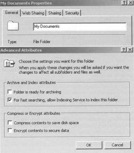 One unique talent possessed by NTFS is the ability to compress and decompress individual files on the fly. Compression allows the file to occupy far less hard drive space in storage than when in use. With some earlier compression techniques, there was always a danger of data corruption. Fortunately, with NTFS, compression and decompression don't carry that risk.
As far back as MS-DOS, computers had the ability to compress the contents of a hard drive and then have the OS decompress the files as they were used. This, however, was an all-or-none undertaking. You either compressed the whole drive, or nothing at all.
With NTFS, you can compress individual files or directories on an as-needed basis. Files that are only infrequently used can be compressed for storage. Some types of files, especially graphics and audio files, are well suited for compression. A typical graphics file can be squeezed down to a fraction of its original size.
NTFS is also capable of using much smaller cluster sizes than FAT systems. Small NTFS partitions can read individual sectors. Yet, like FAT32, NTFS is capable of very large partitions and long file names. The table shows relative partition information for NTFS.
| NTFS File Allocation Unit Size by Partition Size |
| Partition Size | Number of Sectors/Clusters | Cluster Size |
| 0-260MB | 1 Sector | 512 bytes |
| 261MB to 8GB | 8 Sectors | 4K |
| 8GB to 16GB | 16 Sectors | 8K |
| 16GB to 32GB | 32 Sectors | 16K |
| 32GB to 2048GB | 64 Sectors | 32K |
| NTFS is very similar to FAT32 in terms of disk space usage, except for the fact that very small partitions can recognize a single sector as an FAU. |
The versions of NTFS used with NT 4.0 and Windows 2000 are not the same. Windows 2000 uses a newer version. NTFS version 5.0 adds a few new bells and whistles that version 4 didn't support. It can handle the same functions as version 4, including individual file and folder security settings and compression. But in addition, it can also allow an administrator to set drive usage limits for individual users.
The newer version of NTFS also supports the Encryptable File System (EFS). The user is able to take files and render them unreadable to anyone who doesn't possess the decryption key. In order the make sure that hostile departing employees don't encrypt the entire system before they move over to your competitors, Microsoft requires that there be an assigned EFS Recovery Agent delegated, or the process does not work. An EFS Recovery Agent has the necessary permissions to import and export encryption keys, so that the data can be recovered even if the employee is unable or unwilling to do it for you.
This new NTFS also has something called the Distributed File System (DFS) built into it. This actually isn't new to NTFS 5.0. It was available to NTFS 4.0 as an installable file system add-on. With 5.0, however, it's integrated into the file system. DFS allows an administrator to build up a collection of links to various resources, wherever they might happen to reside on the network, and locate them all in a singular server. Users can then browse to those links without having to know the location of the actual files. DFS finds the files for them.
IBM and Microsoft actually worked together to design the High Performance File System for the OS/2 operating system. At the time this file system was released, the two companies were working together to co-develop an operating system that could compete with the Macintosh graphical interface. They were looking for a file system that was a little more user-friendly than FAT16, and might provide a little more horsepower.
It was the first of the PC-compatible file systems to support long file names. It also allowed for non-case-sensitive file names. If you named a file My Novel.doc, it would actually find your file even if you looked for My Novel.doc. This was an improvement over HPFS's primary competitor, the Unix File System, which is case sensitive. It was pretty much everything that NTFS would eventually become (not surprising, since Microsoft co-developed it), but had a few minor issues.
It was incompatible with FAT. Installed onto a dual-boot system with OS/2, an MS-DOS or Windows system could not read the files from the HPFS. HPFS could read FAT, but not the other way around. A bigger problem with versions of MS-DOS prior to 4.01 was that MS-DOS couldn't see even FAT drives that existed downstream from an HPFS drive. For example, if you installed DOS onto drive C, and then OS/2 onto drive D using HPFS, drives E, F, and later couldn't be seen by MS-DOS, no matter what file system they used.
With MS-DOS 4.01 and later, you could see the FAT drives, but there was an additional problem. Since DOS couldn't see the HPFS drive, it effectively didn't exist. Therefore, in the system described above, under HPFS, drive C was MS-DOS, drive D was OS/2, and drives E, F, and later were whatever they happened to be. That same machine, booted to MS-DOS saw drive C, ignored the HPFS drive, and made the next drive it could see drive D. If drive E happened to be HPFS, then the next drive MS-DOS could see would be drive D. To HPFS, that same drive would be drive F. This played havoc on organization.
How did this affect your floppy drives? Not much, actually. By default, HPFS doesn't support removable media. Nobody has ever really considered the floppy disk drive to be a high performance device. Therefore only FAT12 is used with floppy drives. All other file systems can read it.
If you are reading this book specifically for the purpose of preparing for the A+ Core Exam, it is unlikely that you will get any questions relating to this file system. Still, there are a lot of computers out there in the real world that make use of the Unix operating system, and unless you know the basics of the file system used you're going to flounder like a duck on an oil slick.
The Unix File System (UFS) uses a tree structure for sorting directories, subdirectories, and individual files. In fact, I think it's safe to say that other OSs emulated Unix in this manner. With Unix, the root directory is represented by a single /. Beneath the root are several subdirectories. The most common subdirectories seen on a Unix system are as follows:
- /bin: Commands and directories needed by the user
- /dev: Files used to represent specific devices, either installed on the system or remotely connected
- /etc: Commands and utilities used for system administration
- /lib: Libraries used by various programs or programming languages
- /tmp: Temporary files
- /usr: Subdivided into subdirectories; includes the games that ship with Unix and the home directory for each user created on the system
- /Kernel File: Home of the Unix operating system files
UFS breaks the hard drive down into blocks. Depending on the version of Unix being used, blocks will consist of one, two, or four sectors. Data is stored in the blocks.
The file system can be broken down into four distinct components: the boot block, the Super block, the i-node list, and the data blocks. The boot block contains the information needed to initialize the operating system from a cold start. The Super block defines the state of the file system. This would include such information as how many files are already stored, how much available space remains on the device, and permissions associated with the device. The i-node list, usually simply referred to as the i-list, keeps track of the locations of individual files stored on the device. And, as you might imagine, the data blocks are where the data is actually stored.
By default Unix is a network operating system. As such, it must support the ability to service multiple users at once. One of the methods it uses to accomplish this is to assign users their own home directories in the /usr directory. When a user logs onto the system, he or she is automatically directed to the home directory. Unix uses a different method of accessing files than the file systems I discussed earlier in the chapter. Instead of a file system table that maps out specific FAUs on the hard drive, Unix provides a unique file system for each user. The OS opens a separate instance of a root file system for each new user who logs on.
The i-list keeps track of the file systems that are mounted at any given time. The i-list is nothing more than a fixed memory location that contains a list of entries for each file system mounted. For each file system an i-node is generated. It is the i-node that contains the information used by UFS to locate files on the physical storage device. Each i-node can contain up to ten pointers. A pointer is a line of code that maps to a specific block. Each i-node can also contain one indirect pointer, one double-indirect pointer, and one triple-indirect pointer. An indirect pointer maps points to a cluster of pointers.
The ten pointers of an i-node can basically define a 5KB file. For a file larger than 5KB, an indirect pointer maps to a storage block that stores a table of additional block pointers. If an earlier version of Unix is installed, a block points to a single sector of 512 bytes. A pointer uses 4 bytes. Therefore, a table could contain 128 pointers. A 1024-byte block could contain 256 pointers and a 2048-byte block could contain 512. For the purposes of this discussion, I will stick to the 512-byte block. An indirect pointer adds 128 pointers per block, which would allow the system to manage a 64KB file.
Once file size exceeds 641KB a double-indirect pointer will be employed. A double-indirect pointer maintains a table of locations to up to 128 indirect pointers. Since an indirect pointer can map up to 64KB of storage space, a double-indirect pointer would map up to 128 x 64KB, or 8MB.
For files larger than 8MB, the system needs to make use of the services of the triple-indirect pointer. The triple-indirect pointer maps to 128 double-indirect pointers. This allows the UFS to support files up to a gigabyte in size.
As I mentioned earlier, the more recent versions of Unix make use of 2KB blocks. This means each block can contain up to 512 pointers. As a result, UFS can theoretically support up to 64GB files. However, a field contained in the i-node that defines file size is only 4 bytes long. This imposes a 4GB limitation on file size.
Other information stored in each i-node includes the following:
- File owner ID: A number generated by the OS that is used by the security file to identify the specific user on the system who created the file.
- Group ID: This identifies a group of users that can be granted specific levels of access by the owner.
- File type: Files can be listed as any one of several file types. Among these are:
- Regular file: a conventional data file
- D file (directory file): a file that contains file names and their associated i-node numbers
- L file (symbolic link file): a file that contains the path information needed to access a file
- C file (character special file): a file that is intended to be accessed one character at a time. The file associated to your keyboard would be an example of a character file.
- B file (block special file): a file that is accessed a block at a time. The file associated to your monitor is an example of a block special file.
- P file (pipe file): A file associated to a device that streams data into a system, such as a modem or network card. This type of file is usually required by any device that needs to buffer data.
- File access permissions: There are three sets of permissions. User access is automatically granted to the person that owns the file. This is generally the creator, unless someone with administrative privileges has taken ownership. Group access is restricted access granted to any member of a specified group. Other access consists of whatever level of access has been granted to anyone not recognized by user or group access lists. Permissions come in three types as well. Read access allows a user to inspect the data stored in the file, but that user can make no changes or delete the file. Write access allows the user to make changes to the file. Execute access allows the user to run any executable code contained within the file.
An i-node can also keep track of various access times, including the following:
- File access time: This indicates when the file data last opened by the system.
Events that will change this value include the following:
- Displaying the contents of the file
- Copying the file to a new location or file system
- Editing the file
These events will not change this value:
- Moving the file to another directory in the current file system
- Using redirection to append data to an existing file
- File modification time: This indicates when data contained within the file was last changed.
Events that will affect this value include the following:
- Creating the file initializes the value.
- Editing a file and saving it will update this value.
- Overwriting the file with new data will update this value.
- Appending data to an existing file will update this value.
- i-node modification time: This value shows when information in the i-node was last changed.
Events that alter this value include the following:
- Creating additional hard links to the file
- Changes in file size
In Chapter Six, Motherboards, BIOS, and the Chipset, I discussed in some detail the process of POST. I noted that the bootstrap loader locates and runs the Master Boot Record (MBR). The exact content of the MBR varies among operating systems, but the functionality remains the same. For the purposes of this discussion, I will use the FAT16 MBR used by MS-DOS.
In DOS, the MBR consisted of a single sector that held all of the information I will discuss throughout the rest of this section. This sector is located at Cylinder 0, Head 0, Sector 1 of the hard drive. In FAT16, that was the only place the MBR could be located. On the outset, this may seem to contradict what I said earlier about the hard drive reading clusters rather than sectors. Keep in mind, however, that this early in the boot process the file system has yet to be defined. In fact, it is this MBR that defines the file system. System BIOS reads sectors. Therefore, programmers had to fit all that information onto a single sector. One of the advances of different 32-bit file systems was that they could extend the MBR to two sectors, rather than just one.
The information stored on the MBR (see the following table) tells the system several things. It defines the file system to be used. This is a string of executable code that once run, remains resident in memory. This code tells the computer which file system you chose when you first prepared your hard drive. This code is added to the MBR during the FDISK process in MS-DOS and Windows or by similar third-party utilities.
| Contents of the MBR |
| Process | Size of Process | Location on Drive |
| Boot Code (Defines file system and boots computer) | 446 bytes | 000h |
| First Partition Table | 16 bytes | 1BEh |
| Second Partition Table | 16 bytes | 1CEh |
| Third Partition Table | 16 bytes | 1DEh |
| Fourth Partition Table | 16 bytes | 1EEh |
| Executable Marker | 2 bytes | 1FEh |
| The MBR contains several specific pieces of information that the system requires in order to boot. |
Next come the partition tables. If desired, a user can subdivide the available space on a disk into multiple logical sections called partitions. To the user, each partition appears as a separate hard disk, or logical drive.
Partition tables contain 16-byte blocks of data for each partition that exists on the hard drive. 16 bytes doesn't sound like a lot, but as you can see in the table, it manages to do a lot. A FAT16-formatted drive could contain up to four partition entries. The First would be the primary partition for that drive while the subsequent partitions will be extended partitions. There could be additional logical drive entries because each of the extended partitions contains an entry similar to the MBR called the volume boot record (VBR). The VBR is not limited to one sector and therefore can define as many logical drives as the user chooses to configure.
| Contents of a Partition Table (First Primary Partition) |
| Process | Size of Process | Location on Drive |
| Partition State (active/inactive) | 1 byte | 00h |
| Begin Partition (which head) | 1 byte | 01h |
| Begin Partition (cylinder/sector) | 2 bytes | 02h |
| Partition Type | 1 byte | 04h |
| End Partition (which head) | 1 byte | 05h |
| End Partition (cylinder/sector) | 2 bytes | 06h |
| Sectors between MBR and Partition | 4 bytes | 08h |
| Number of Sectors in Partition | 4 bytes | 0Ch |
| Relative location of data for 2nd, 3rd, and 4th partitions is offset by 16 bytes from these positions. |
| The reason boot sector viruses are so dangerous is that, as you can see from this table, changing just a single bit of data can make it impossible for the hard disk controller to accurately locate a partition. |
Following the partition tables is a marker that indicates the location of the first lines of executable code for the operating system. This is the executable marker, and it is only a 2-byte entry in MS-DOS.
Once the file system has been loaded, the drive will now be read in clusters rather than individual sectors. The FAT occupies the sectors of the hard drive directly following the MBR. FAT16 generated two different copies of the tables, while FAT32 generates four. The purpose of the FAT is to identify the locations of all clusters that contain data for a specific file. Every single cluster on the drive is assigned a FAT entry, whether it initially contains data or not.
Each FAT entry will consist of a 16-bit entry (hence the name FAT16) that defines the usage of that particular cluster. That entry will have certain information telling the system whether or not there is data in the cluster, if the cluster has been marked bad, and if another cluster elsewhere also holds data relevant to that file. If so, the directory table will point the direction to the next cluster for that file.
This table details the possible entries that would describe a cluster:
| Defining Clusters |
| FAT Entry (range) | Definition |
| 0000h | Cluster is empty. |
| 0002h-FFEFh | Cluster is used; points to next cluster in file. |
| FFF0h-FFF6h | Cluster is reserved. |
| FFF7h | Cluster is marked "bad". |
| FFF8h-FFFFh | Cluster is used and is the last cluster in file.
This is the End of File Marker. |
| The entries in the FAT have specific functions. |
The directory tables and the file allocation tables are not the same thing. The directory table maintains a list of file names and all of the information associated with those files that lets the operating system know how to deal with them. Each file name takes up eight bits, the extension another three bits. Directory attribute information is stored in a single bit and will include such information as whether the file is hidden, or read only, whether it has been archived or not, and whether it constitutes a system file or not. A subdirectory is treated as if it is a file by the directory tables, except that it is assigned a directory attribute.
In addition to attribute information, the directory tables store information that tells the system the time and date that the file was created, what cluster to go to, and finally, the overall size of the file. This last bit of information sends the disk controller back to FAT to look up the next cluster in that file, if the End of File (EOF) marker has not been reached. The original FAT16 file system provided for a 32-bit entry for each file or directory, yet only made use of 22 bytes.
The layout of a typical directory entry is detailed in this table:
| FAT16 Directory Table Entries |
| Table Entry Value | Size of Entry |
| File Name | 8 bytes |
| File Extension | 3 bytes |
| File Attribute | 1 byte |
| Time | 2 bytes |
| Date | 2 bytes |
| Cluster Location | 2 bytes |
| File Size | 4 bytes |
| A listing of the functions in a file table entry for FAT16
|
When manufacturers made the move to FAT32, they opened up the possibility of those long file names I discussed earlier. The file allocation tables not only have to deal with much longer file names, but also create an 8.3 file name compatible with older applications. With FAT32, those 8.3 entries were redesigned to make use of all 32 bits available to the entry. This allowed the directory table to provide additional information, including far more refined time and date information, as well as the ability to tell when the file was last accessed and not simply when it was created.
Summary
- This chapter introduced you to the technology behind hard drives. As with most of the chapters of this book, I provided far more detail than is required simply to pass the A+ Exam. I discussed how hard drives are made and covered some of the key components of the hard drive. I also introduced you to some of the different file systems that have been used, past and present.
- As hard drives evolve, so must file systems, system BIOS, and the operating systems. As you will see in the next chapter, hard drives haven't always been the humongous high-speed devices you enjoy today.
A+ Exam Objectives
Some exam objectives to be covered in this chapter include the following:
- Identify the names, purpose, and characteristics of system modules. Recognize these modules by sight or definition.
- Identify basic procedures for adding and removing field-replaceable modules for desktop systems. Given a replacement scenario, choose the appropriate sequences.
- Identify typical IRQs, DMAs, and I/O addresses, and procedures for altering these settings when installing and configuring devices. Choose the appropriate installation or configuration steps in a given scenario.
- Identify the names, purposes, and performance characteristics of standardized/common peripheral ports, associated cabling, and their connectors. Recognize ports, cabling, and connectors by sight.
- Identify proper procedures for installing and configuring common IDE devices. Choose the appropriate installation or configuration sequences in given scenarios. Recognize the associated cables.
- Identify procedures to optimize PC operations in specific situations. Predict the effects of specific procedures under given scenarios.
- Determine the issues that must be considered when upgrading a PC. In a given scenario, determine when and how to upgrade system components.
- Recognize common problems associated with each module and their symptoms, and identify steps to isolate and troubleshoot the problems. Given a problem situation, interpret the symptoms and infer the most likely cause.
- Identify the various types of preventive maintenance measures, products, and procedures, and when and how to use them.
Tricky Terminology
- Areal density:
- The total amount of storage capacity for a specific unit of area on the surface of the drive platter.
- Average access time:
- The amount of time required by a disk drive to lock on to the first sector that contains data requested by the controller.
- Average seek time:
- The amount of time it takes to locate and lock on to the first track that contains data requested by the controller.
- Bit cell:
- The collection of magnetized particles that comprise a single bit on magnetic media.
- Block:
- The number of sectors on a hard drive that UFS uses as the smallest recognizable data unit.
- Burst mode:
- The speed at which data moves from the RIW heads to a drive's buffer memory. Also known as internal host transfer rate.
- Cluster:
- The minimum number of sectors a specific file system can recognize as a single data unit. Another term for file allocation unit.
- Cylinder:
- A virtual structure created by the tracks that line up vertically on the surface of each of the platters.
- Data encoding mechanism:
- The method used by a device to convert digital information into an electronic format recognizable by the target device.
- Directory attribute:
- A single bit that identifies an entry in the directory table as being a subdirectory rather than a file.
- Directory table:
- A database of all file names on a hard drive and the partitions with which they are associated. Other information pertaining to file system security is also contained here.
- Drive translation:
- A technique by which an address space beyond what Intl 3h can read is converted into something that it can understand.
- Executable marker:
- A pointer in the MBR that directs the boot sequence to the first line of code for the primary kernel file of the OS installed.
- External host rate:
- How fast data moves from a drive's controller to RAM.
- File system:
- The mechanism used by a hard drive to map the specific sectors used by any given file.
- Floating height:
- The distance above a hard drive's platter that the RIW heads hover as the platter spins beneath.
- Flux reversal:
- A transition of magnet charge from a positive to a negative state, or vice versa.
- Head crash:
- A disastrous event caused by the RIW head in a drive coming into physical contact with the platter while it is spinning.
- Head parking:
- A process of positioning RI W heads in a hard drive in a place where contact with the platter will do no harm.
- Int13h extensions:
- Additional instructions added to the BIOS that intercept hard disk I/O operations and provide the drive translation required by hard disks larger than 8GB.
- Internal host rate:
- The speed at which data moves from the R]W heads to a drive's buffer memory. Also known as burst mode.
- Landing zone:
- An area on the hard disk's platter where the R/W heads can be safely parked.
- Latency:
- The delay that occurs from the time the CPU makes a request for data and the time that information can be accessed from the device holding the data. All devices, including memory and hard drives, exhibit latency.
- Logical drive:
- A section of disk space isolated from the rest of the same physical disk so that it appears to the user as a separate disk drive.
- Partition:
- Logical sections on a hard disk that divide the overall disk space into multiple logical drives.
- Platter:
- One of two or more physical disk structures installed in a typical hard drive.
- Pointer:
- A line of code used by UFS to map a cluster used by a specific file.
- Thin-film metal:
- A metalized magnetic medium applied by evaporating metal and allowing it to "condense" back onto the surface being coated.
- Transition cell:
- The minimum number of particles that can be affected by a single magnetic flux.
- Vapor deposition:
- The process of applying a metal coating by the process of evaporation.
- Voice coil:
- An extremely fast and highly accurate motor that works by applying an electrical current to a tightly wrapped coil of wires surrounding, but not touching, a permanently magnetized cylinder. When current is applied to the coil, the cylinder rotates. Negative voltage rotates the cylinder one direction, positive the other. The amount of voltage determines how far the cylinder moves.
- Zone bit recording:
- A technology that allows the sectors on the outer tracks of a hard disk to be the same physical size as those toward the center. This allows for far more sectors per track on the outer tracks.
Acronym Alert
- CHS:
- Cylinders, Heads, Sectors-per-track. The parameters of hard drive configuration that define total capacity of the drive as well as specific locations on the drive.
- DFS:
- Distributed File System. A subset of NTFS that allows users to browse to remote resources on a network without requiring the user to know the specific path information.
- DTR:
- Data Transfer Rate. How fast information moves from one device to another.
- EFS:
- Encryptable File System. A subset of NTFS that allows individual files to be scrambled on an as-needed basis and subsequently unscrambled only by a user with appropriate permissions.
- ENDEC:
- Encoder/Decoder
- EPRML:
- Extended PRML. A data encoding mechanism used by most hard disk drives currently being manufactured.
- FAT:
- File Allocation Table. A file on a disk, hidden from the user, that identifies what file is using each sector on the disk. It is the disk's roadmap, if you will.
- FAU:
- File Allocation Unit. The smallest usable amount of drive space in sectors used by a file system for a single file, regardless of how small that file may be.
- HPFS:
- High Performance File System
- IOPS:
- I/O Operations Per Second. The maximum number of times a device can receive and then execute either a request for data or a request to write data to the device, assuming the smallest block of data the device utilizes.
- LFN:
- Long File Names
- MFM:
- Modified Frequency Modulation. One of the early data encoding mechanisms used by hard disk drives.
- NTFS:
- New Technology File System
- PRML:
- Partial Response/Maximum Likelihood. A data encoding mechanism used by more recent hard disk drives.
- R/W:
- Read/Write
- RLL:
- Run Length Limited. One of the early data encoding mechanisms used by hard disk drives.
- UFS:
- Unix File System
- VBR:
- Volume Boot Record